

UPDATE!. I have had an issue with hot end temperature stability since doing this upgrade, and have now switched to an MKS GEN 1.4 board which is performing much better. See the new guide here
In this post, I am going to cover what is needed to replace the ‘Ender 3 Pro’s control board with an MKS GEN L board running Trinamics TMC2208 drivers in UART mode.
I’m not going to go to in depth on the re-wiring, as teaching tech have already done an excellent video on this, instead, I am going to concentrate on setting up the TMC2208s as there is not an awful lot of info on this! Follow the video below except for the drivers and firmware parts – I’ll cover that in a bit. You will also want to print an adapter plate or new control box housing.
Once done there are a couple of things needed before installing the drivers.
You will need some 1Kohm resistors and some Dupont cables .
The next step we do with the stepper motors unplugged from the mainboard, please do this as you could fry them otherwise!!
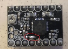
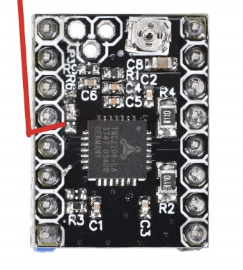
First things first, we need to move the PDN pin on the TMC2208 so it is pointing upwards, this will allow us to plug the Dupont connector on easily, a little like this: (note yours will probably look different)

The way I did this was to heat up the solder holding the pin on the top of the board, and gently squeeze it through with a pair of needle-nosed pliers.
We also need to solder a jumper pad on the top of the board to enable the pin – join the two pads carefully with a blob of solder
Next, we need to may some Y cables:
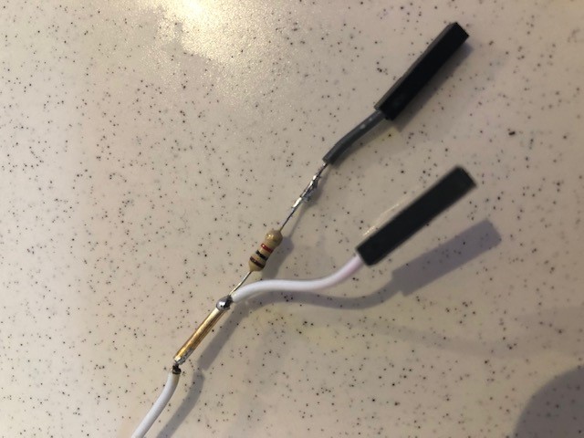
Use some heat shrink or electrical tape to insulate the bare wires and resistor,

Place the heatsinks carefully on the chip on the top, taking great care not to let it touch any of the other components (I missed one and managed to fry the driver in the process, so check, check and double-check!)
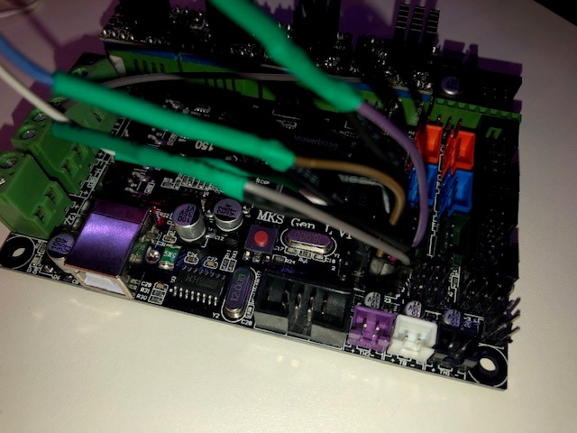
Now we need to mount the boards on our MKS GEN L, note the orientation:

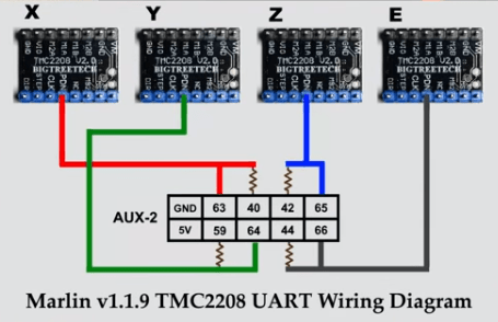
The diagram below shows how the jumper wires should be connected to the board:
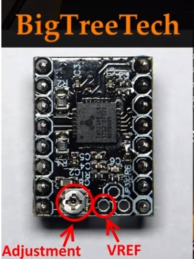
Ok, so a couple more things to do here – although the current is set from firmware, we need to set the vref voltage so that there is enough ‘range’ for the firmware to operate in. I set all of mine to 1.1v
Turn on the power to the board. Unless you are using a ceramic tipped screwdriver, I recommend you take a reading, turn the power off, turn the Adjustment screw slightly, then turn back on and re-measure. Repeat this process until you are happy with the settings. On mine, I had to turn anti-clockwise to increase the voltage.
Use the positive tip of your multimeter on the VREF pad, and put the negative tip on the USB shield to get a reading.
Note on the Ender 3 display – plug the lead into the upper LCD connector on the board, (the one on the right of the red endstop connector in my picture) on the LCD end of the cable you need to remove the cable, cut the lug off, rotate it 180 degrees and re-insert it.
Once you have done all 4, we need to make some tweaks in Marlin. I used the 1.1.9 vanilla firmware for this.
We also need to add the TMC2208 library to Arduino
Go to tools and library manager and search for TMC2208 and click install
 .
.
Now we get editing!
Find the motherboard section in configuration.h (around line 133) and set like this:
#ifndef MOTHERBOARD
 #define MOTHERBOARD BOARD_MKS_GEN_L
 #endif
Line 152
#define DEFAULT_NOMINAL_FILAMENT_DIA 1.75
Pid settings (around line 383)
#define DEFAULT_Kp 21.73
 #define DEFAULT_Ki 1.54
 #define DEFAULT_Kd 76.55
Stepper drivers section (around line 553)
#define X_DRIVER_TYPE TMC2208
 #define Y_DRIVER_TYPE TMC2208
 #define Z_DRIVER_TYPE TMC2208
 //#define X2_DRIVER_TYPE A4988
 //#define Y2_DRIVER_TYPE A4988
 //#define Z2_DRIVER_TYPE A4988
 #define E0_DRIVER_TYPE TMC2208
 //#define E1_DRIVER_TYPE A4988
 //#define E2_DRIVER_TYPE A4988
 //#define E3_DRIVER_TYPE A4988
 //#define E4_DRIVER_TYPE A4988
Then around line 611
#define DEFAULT_AXIS_STEPS_PER_UNIT { 80, 80, 400, 93 }
Line 626
#define DEFAULT_MAX_ACCELERATION { 500, 500, 100, 5000 }
/**
 * Default Acceleration (change/s) change = mm/s
 * Override with M204
 *
 * M204 P Acceleration
 * M204 R Retract Acceleration
 * M204 T Travel Acceleration
 */
 #define DEFAULT_ACCELERATION 500 // X, Y, Z and E acceleration for printing moves
 #define DEFAULT_RETRACT_ACCELERATION 500 // E acceleration for retracts
 #define DEFAULT_TRAVEL_ACCELERATION 500 // X, Y, Z acceleration for travel (non printing) moves
Next around line 843 we have to invert the stepper directions:
// Invert the stepper direction. Change (or reverse the motor connector) if an axis goes the wrong way.
 #define INVERT_X_DIR false
 #define INVERT_Y_DIR false
 #define INVERT_Z_DIR true
// @section extruder
// For direct drive extruder v9 set to true, for geared extruder set to false.
 #define INVERT_E0_DIR false
 #define INVERT_E1_DIR false
 #define INVERT_E2_DIR false
 #define INVERT_E3_DIR false
 #define INVERT_E4_DIR false
Set print bed size around line 884
// The size of the print bed
 #define X_BED_SIZE 230
 #define Y_BED_SIZE 230
// Travel limits (mm) after homing, corresponding to endstop positions.
 #define X_MIN_POS 0
 #define Y_MIN_POS 0
 #define Z_MIN_POS 0
 #define X_MAX_POS X_BED_SIZE
 #define Y_MAX_POS Y_BED_SIZE
 #define Z_MAX_POS 250
Check line 1229 EEPROM settings are correct
#define EEPROM_SETTINGS // Enable for M500 and M501 commands
 //#define DISABLE_M503 // Saves ~2700 bytes of PROGMEM. Disable for release!
 #define EEPROM_CHITCHAT // Give feedback on EEPROM commands. Disable to save PROGMEM.
Line 1751:
#define CR10_STOCKDISPLAY
Now move to configuration_adv.h
line 240
#define E0_AUTO_FAN_PIN 7
Line 1100:
#define R_SENSE 0.11 // R_sense resistor for SilentStepStick2130
 #define HOLD_MULTIPLIER 0.5 // Scales down the holding current from run current
 #define INTERPOLATE true // Interpolate X/Y/Z_MICROSTEPS to 256
 #define X_CURRENT 700 // rms current in mA. Multiply by 1.41 for peak current.
 #define X_MICROSTEPS 16 // 0..256
#define Y_CURRENT 700
#define Y_MICROSTEPS 16
#define Z_CURRENT 700
 #define Z_MICROSTEPS 16
Line 1153
#define STEALTHCHOP
Line 1166
#define MONITOR_DRIVER_STATUS
Line 1180
#define HYBRID_THRESHOLD
 #define X_HYBRID_THRESHOLD 200 // [mm/s]
 #define X2_HYBRID_THRESHOLD 100
 #define Y_HYBRID_THRESHOLD 200
 #define Y2_HYBRID_THRESHOLD 100
 #define Z_HYBRID_THRESHOLD 3
 #define Z2_HYBRID_THRESHOLD 3
 #define E0_HYBRID_THRESHOLD 30
 #define E1_HYBRID_THRESHOLD 30
 #define E2_HYBRID_THRESHOLD 30
 #define E3_HYBRID_THRESHOLD 30
 #define E4_HYBRID_THRESHOLD 30
Line 1218
#define TMC_DEBUG
Make sure you have set the board and processor as per below:
Thats it, you should be good to compile and upload.

Once uploaded, use the Marlin serial monitor, making sure the baud rate is set like this: 
and issue M502, then M500 to reload the default settings and store the new settings.
Now issue the M122 command and you should get something similar to this, Note ENABLED is true for all Axis with a TMC2208 in UART mode. If it doesn’t say true, check your wiring! (My extruder is missing as I fried the chip and am still waiting for a replacement!)

Next steps, you will need to reconfigure the BLtouch if you have one (or any other probe) and re-set your Z offset.
I’ll upload my already edited firmware shortly if you are not comfortable editing.
Thanks I got it thanks to your instructions! but first I had to use the version 1.19 bugfix now everything is set to true
Hi Jimmy!
May I ask you one stupid question?
If I have stock Ender 3 Pro temperature sensors, have I use “#define TEMP_SENSOR_0 1” or “#define TEMP_SENSOR_0 5” like in your example?
Thanks in advance!
Hi !
#define TEMP_SENSOR_0 1
for the standard sensor 🙂
Hi!
Thanks!
One more question, is it possible to use “#define STEALTHCHOP” for TMC2100 ?
That I am unsure of, I am not familiar with that chip, sorry.